
Fundamentals and Technology of Abrasive Flow Machining – AFM
Introduction
Abrasive flow machining was developed independently by two US-American companies in the 1960s. Initially, the main field of application was the finishing of high-alloy components with complex geometries in aerospace. With this method it became possible to substitute various time-consuming manual deburring and polishing operations that had often lead to non-reproducible work results. Today, abrasive flow machining is used as a finishing method in a number of fields for diverse metal components with complex geometries. The method is applied for a manufacture of high surface qualities on inner and outer contours, for specific deburring and for a defined radiusing with reproducible work results.
Processes and classification
The tool is made of a semi-solid polymere, the so-called base, in which the abrasive grains are bonded. With the use of additives, the medium shows defined properties that are adapted to the individual task. The grinding agents used are aluminum oxide, silicon carbide, boron carbide or diamond. An alternating motion along the machined surfaces and edges is forced upon this medium and leads to the material removal. This method has not yet been registered in the method classifications DIN 8580 and DIN 8589. As the mechanisms leading to the material removal in abrasive flow machining have not yet been fully investigated, this method can merely be classified as removing manufacturing process with geometrically undefined cutting edges.
Before machining, the work medium is placed in the lower cylinder of the AFM-machine (Illustration 1a). The work piece which is situated in a special fixture, which is squeezed hydraulically into the area between the two pistons. During the machining process, the lower piston first moves at a defined pressure from the lower to the upper dead centre (Illustration 1b). At this point, no pressure is exerted on the upper piston. The medium flows along the work piece surfaces and edges that are to be machined. Afterwards the work pressure is exerted on the upper piston and the medium flows along the contours of the work piece, in the direction from the upper to the lower cylinder (Illustration 1c). A complete motion of the medium from the lower to the upper cylinder and back is called a cycle.
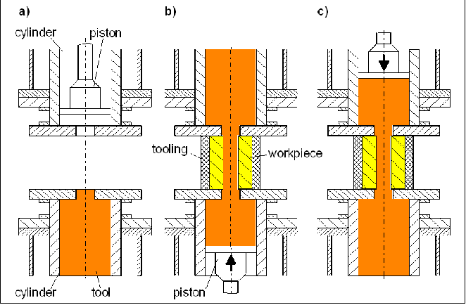
Illustration 1: Processes during abrasive flow machining
Objectives and further steps
For abrasive flow machining, neither the occurring mechanisms concerning the surface formation nor the flow conditions have so far been fully clarified. Within the scope of the project carried out at the IWF, the basic correlations between the initial states of the work pieces, the setting parameters, the composition of the abrasive medium, the wear state of the fluid and the obtainable work result are initially investigated. In order to analyze the flow processes occurring during this method, the rheologic properties of the applied fluids have to be studied. Based on these results, a flow model is designed which can later be used to simulate flow processes with CFD programs (Computational Fluid Dynamics). The aim of such a simulation is to optimize the tooling, the setting parameters as well as the composition of the medium. The results of the flow simulation are verified using model tests. In the course of the technological investigations planned, the influence of the process parameters, the raw state of the work pieces, the tool specification and the wear state of the medium on the obtainable surface qualities, the geometrical accuracy, the deburring result and the sub-surface properties will be determined. With the results from the basic investigations and the technological investigations, a technological counselling model will be developed. In the future this model can be applied for a process layout of abrasive flow machining, rendering expensive and time consuming preliminary tests unnecessary.
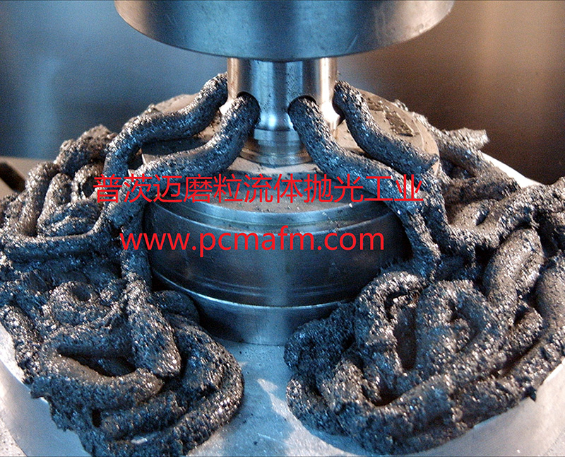
Illustration 2: Brass nozzle deburred with abrasive flow machining (left) compared to a non-machined workpiece
